
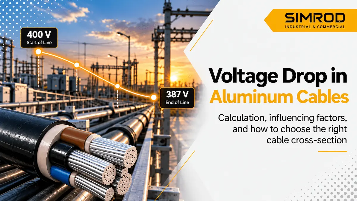
Aluminum Cable Voltage Drop: Calculation and Proper Cable Size Selection
Imagine an electrical panel, motor, or industrial load located relatively far from its power source. The voltage at the beginning of the cable may be appropriate, but the voltage measured at the end of the cable, at the point of consumption, is lower.
Part of this difference is known as cable voltage drop.
An electrical conductor does not have zero resistance or impedance. When current flows through a cable, part of the voltage is lost along the cable length. Therefore, when designing an electrical circuit, it is not enough to determine whether the cable has sufficient current-carrying capacity. The voltage available at the end of the cable must also remain within an acceptable range.
This issue is particularly important when using aluminum cables, because aluminum has higher electrical resistivity than copper. Therefore, copper and aluminum cables with the same cross-sectional area cannot simply be considered equivalent in terms of voltage drop. In approximate calculations presented in Schneider’s IEC-based guide, resistance coefficients of 37.6 Ω·mm²/km for aluminum and 23.7 Ω·mm²/km for copper are used.
In this article, we examine how cable voltage drop is calculated, which factors increase it, and how to select the appropriate cross-sectional area for an aluminum cable.
What Is Cable Voltage Drop?
When electric current flows through a conductor, the impedance of the conductor creates a voltage difference between the beginning and end of the cable.
This difference is known as:
Voltage Drop
For example, if the voltage at the beginning of a circuit is 400 volts but the voltage measured at the end of the circuit under load is 390 volts:
Voltage Drop = 10 volts
The voltage-drop percentage is calculated as:
Voltage Drop (%) = (Voltage Drop ÷ Rated Voltage) × 100
Therefore, in the example above:
(10 ÷ 400) × 100 = 2.5%
As voltage drop increases, the actual voltage available to the load moves further away from the expected voltage.
Why Is Voltage Drop Important?
A cable may have an adequate current-carrying capacity and still not be the right choice for a particular project.
For example, suppose a cable is capable of carrying 100 amps. If the same cable is installed over a very long route, the voltage drop at the end of the cable may exceed the acceptable limit.
Therefore, at least two independent checks should be performed when selecting a cable:
- Cable current-carrying capacity
- Voltage drop along the cable route
In a complete electrical design, other factors such as short-circuit protection, installation conditions, ambient temperature, and applicable standards must also be considered.
What Factors Increase Cable Voltage Drop?
Four main factors have a significant effect on voltage drop.
1. Cable Length
The longer the cable route, the greater the total resistance of the circuit.
Therefore:
Longer cable route → Higher voltage drop
For this reason, a cable that is suitable for a 20-meter route is not necessarily suitable for the same load over a 200-meter route.
2. Current
As the current flowing through the cable increases, voltage drop also increases.
Therefore, if the actual load of a project is greater than originally estimated, the resulting voltage drop may also increase.
3. Cable Cross-Sectional Area
Increasing the conductor cross-sectional area reduces conductor resistance.
Therefore, in general:
Larger cross-sectional area → Lower resistance → Lower voltage drop
This is why a designer may sometimes need to select a cable with a larger cross-sectional area than what would be required based solely on current-carrying capacity.
4. Conductor Material
Copper and aluminum do not have the same electrical resistance.
For the same cross-sectional area and cable length, an aluminum conductor has higher resistance than a copper conductor. Therefore, if a copper cable is replaced with an aluminum cable, the comparison should be based on electrical calculations rather than simply selecting the same cross-sectional area.
Aluminum Cable Voltage Drop Calculation Formula
For accurate AC calculations, conductor resistance, reactance, power factor, and circuit configuration must be taken into account.
For a balanced three-phase circuit, a commonly used formula is:
ΔU = √3 × I × L × (R cosφ + X sinφ)
Where:
- ΔU = Voltage drop in volts
- I = Current in amperes
- L = Cable route length
- R = Conductor resistance
- X = Cable reactance
- cosφ = Load power factor
For a single-phase circuit, the formula includes the outgoing and return paths and is commonly expressed as:
ΔU = 2 × I × L × (R cosφ + X sinφ)
These relationships are used in IEC-based electrical installation design guides for calculating voltage drop under steady-state load conditions.
Note: The units used for L and R/X must be consistent. For example, if R is expressed in Ω/km, the cable length must also be entered in kilometers.
How Is the Resistance of an Aluminum Cable Calculated?
For a simple estimation, conductor resistance is related to the following formula:
R = ρ / S
When cable length is also included in the calculation, total resistance depends on the material resistivity, cable length, and conductor cross-sectional area.
In simple terms:
Resistance is directly proportional to length and inversely proportional to cross-sectional area.
This means:
- Longer cable → Higher resistance
- Larger cross-sectional area → Lower resistance
In Schneider’s approximate calculation guide, the following relationship is provided for aluminum:
R ≈ 37.6 / S Ω/km
where S is the conductor cross-sectional area in square millimeters.
This value is a design approximation. For final project calculations, it is preferable to use the actual cable resistance provided in the manufacturer’s datasheet and account for the relevant conductor temperature.
IEC 60228 also specifies nominal cross-sectional areas and conductor resistance requirements for copper, aluminum, and aluminum-alloy conductors used in insulated cables.
A Simple Example of Aluminum Cable Voltage Drop
Suppose an industrial project has the following conditions:
- System: Three-phase
- Voltage: 400 V
- Current: 100 A
- Cable length: 100 m
- Aluminum conductor cross-sectional area: 50 mm²
To keep the example simple, assume a power factor of approximately 1 and ignore the effect of reactance.
The approximate conductor resistance is:
R = 37.6 ÷ 50 = 0.752 Ω/km
Cable length:
100 m = 0.1 km
Therefore:
ΔU ≈ √3 × 100 × 0.1 × 0.752
The result is approximately:
13 V
Therefore, the voltage-drop percentage is:
13 ÷ 400 × 100 ≈ 3.25%
Now, if the conductor cross-sectional area is increased without changing the current or cable length, conductor resistance decreases, and consequently the voltage drop also decreases.
This example demonstrates why selecting a cable based solely on amperage is not sufficient.
This example is provided for educational purposes and does not replace project design calculations, manufacturer datasheets, or an assessment of actual installation conditions.
What Is the Permissible Cable Voltage Drop?
There is no single fixed value that applies to every project. The applicable regulations, standards, and project specifications must be reviewed.
As an international reference, the Electrical Installation Guide, based on IEC 60364-5-52, indicates typical values of 3% for lighting circuits and 5% for other power and heating applications in low-voltage installations supplied directly from a public LV network.
For installations supplied by a private LV source, different reference values may apply.
These limits also relate to steady-state operating conditions and do not necessarily cover transient conditions such as motor starting.
Therefore, it is incorrect to state:
“The permissible voltage drop is always 3%.”
The acceptable value should be determined according to the circuit type, project regulations, applicable standards, and the requirements of the connected equipment.
How Is Three-Phase Cable Voltage Drop Calculated?
In industrial projects, calculating voltage drop in a three-phase system is one of the most common requirements.
For a balanced load, the following formula can be used:
ΔU = √3 × I × L × (R cosφ + X sinφ)
Current and cable length alone are not sufficient for an accurate calculation.
The following parameters should also be considered:
- Actual cable resistance
- Reactance
- Power factor
- Conductor temperature
- Actual cable route length
For this reason, online calculators that require only “amperage + cable length” may be useful for preliminary estimates, but they cannot necessarily replace an engineering calculation.
How Is Single-Phase Cable Voltage Drop Calculated?
In a single-phase circuit, current travels through both the outgoing and return paths.
The commonly used formula is:
ΔU = 2 × I × L × (R cosφ + X sinφ)
This is one of the reasons why cable route length is particularly important when selecting the conductor cross-sectional area for a single-phase cable.
Simple Table Showing the Effect of Cross-Sectional Area on Voltage Drop
To better understand the concept, assume that all conditions remain constant and only the aluminum conductor cross-sectional area changes.
| Cross-Sectional Area | Approximate Conductor Resistance | Relative Voltage Drop |
|---|---|---|
| 25 mm² | Higher | Higher |
| 35 mm² | ↓ | Lower |
| 50 mm² | ↓ | Lower |
| 70 mm² | ↓ | Lower |
| 95 mm² | ↓ | Lower |
| 120 mm² | ↓ | Lower |
The key principle illustrated by this table is:
When all other parameters remain constant, increasing the cross-sectional area reduces conductor resistance and therefore reduces voltage drop.
However, this table is not a cable-sizing table. Final cable selection must consider current-carrying capacity, installation method, thermal conditions, voltage drop, and other project requirements simultaneously.
The installation method is also an important factor in determining cable current-carrying capacity.
How to Select the Cross-Sectional Area of an Aluminum Cable
One common mistake is to ask:
“What size aluminum cable do I need for 100 amps?”
This question does not provide enough information.
At a minimum, cable selection requires:
Current + Voltage + Cable Length + Single-Phase/Three-Phase + Installation Method + Environmental Conditions + Permissible Voltage Drop
Therefore, two projects may both have a 100-amp load but require different conductor cross-sectional areas.
Step 1: Determine the Design Current
First, the actual circuit design current must be calculated.
Step 2: Check the Cable Current-Carrying Capacity
The selected cable must have sufficient current-carrying capacity considering the installation method and environmental conditions.
Step 3: Calculate Voltage Drop
After making an initial cross-sectional-area selection, calculate the voltage drop along the cable route.
Step 4: Adjust the Cross-Sectional Area
If voltage drop exceeds the acceptable value, the conductor cross-sectional area may need to be increased.
Step 5: Check Other Protection Requirements
The final cable selection must also comply with the project’s protection requirements and technical specifications.
Why Should a Larger Cable Be Selected for Long Cable Routes?
Suppose there are two identical loads.
The first load is located 20 meters from the electrical panel.
The second load is located 300 meters away.
Both loads may consume the same current, but the total resistance of the second cable route is significantly higher.
As a result, if the same cable is used for both loads, the second installation will experience greater voltage drop.
In such a situation, the designer may need to select a larger conductor cross-sectional area—not because the smaller cable is incapable of carrying the required current, but because a larger conductor is needed to control voltage drop at the end of the route.
This consideration is particularly important in:
- Industrial projects
- Mining operations
- Large facilities
- Manufacturing sites
- Long distribution routes
Is Increasing Cable Size Always the Best Way to Reduce Voltage Drop?
No.
Increasing conductor cross-sectional area is an effective solution, but it is not the only option.
Depending on the project, the following approaches may also be considered:
- Reducing the cable route length where possible
- Optimizing electrical panel locations
- Increasing conductor cross-sectional area
- Using parallel cables where appropriate
- Improving power factor where relevant
- Reviewing the overall electrical distribution architecture
Therefore, if a project has an unusually high voltage drop, the entire cable route and distribution design should be reviewed before simply purchasing a much larger cable.
In some cases, relocating electrical equipment may be more economical than purchasing a large quantity of oversized cable.
Aluminum or Copper Cable for Long Cable Routes?
There is no universal answer to this question.
For the same cross-sectional area, copper has lower electrical resistance. Therefore, if two cables with identical cross-sectional areas are compared under the same conditions, the copper cable will have lower voltage drop.
However, a real project should compare technically equivalent designs, rather than simply comparing cables with the same cross-sectional area.
For example, instead of using a copper cable with a particular cross-sectional area, a larger aluminum cable may be selected to meet the project’s electrical requirements.
The following factors should then be compared:
- Cable price
- Weight
- Cross-sectional area
- Connection equipment
- Installation conditions
- Installation cost
Therefore, the conclusion that “copper always provides the more economical solution because it has lower voltage drop” is not necessarily correct.
7 Common Mistakes When Selecting a Cable Based on Voltage Drop
1. Selecting a Cable Based Only on Current
Current-carrying capacity is only one of the cable-selection criteria.
2. Ignoring Cable Route Length
100 amps over 20 meters is not the same design problem as 100 amps over 300 meters.
3. Replacing a Copper Cable with an Aluminum Cable of the Same Cross-Sectional Area
These two conductor materials have different electrical resistance.
4. Using One Fixed Percentage for Every Project
The permissible voltage drop depends on the circuit type and applicable project standard.
5. Ignoring Power Factor
In accurate AC calculations, power factor and reactance affect voltage drop.
6. Using a Table Without Considering Installation Method
Installation method affects cable current-carrying capacity and cable selection.
7. Selecting a Cable Based Only on Price per Meter
A cheaper cable with an inadequate cross-sectional area may ultimately be an uneconomical choice.
What Information Should You Provide When Requesting an Aluminum Cable Quotation?
If the cable is being purchased for an actual project, instead of asking a general question such as:
“How much does an aluminum cable cost?”
it is better to provide the sales department with detailed technical information.
At a minimum, the following information is useful:
- Network type: single-phase or three-phase
- Voltage
- Load current or power
- Cable route length
- Required cross-sectional area, if already determined
- Number of cores
- Required cable quantity
- Installation type and location
- Project specification
- Delivery location
If the cross-sectional area has not yet been determined, providing the current, route length, and project specifications allows the supplier to perform a more accurate technical assessment.
Requesting an Aluminum Cable Quotation for a Project
In industrial projects, selecting the wrong cable is not simply a matter of purchase price.
A smaller cross-sectional area may appear attractive because of its lower initial cost, but if it does not satisfy current-carrying capacity, voltage-drop, or installation requirements, it is not the correct choice.
On the other hand, selecting an unnecessarily large conductor can also increase the overall project cost.
Therefore, the objective is not to purchase the largest possible cable. The objective is to select a cable that matches the actual conditions and requirements of the project.
To obtain technical information and request an aluminum cable quotation, provide the network type, current or power, cable route length, required quantity, and project specifications to the Sīm-Rād Sama sales department.
Frequently Asked Questions About Aluminum Cable Voltage Drop
What is aluminum cable voltage drop?
It is the voltage difference between the beginning and end of a cable when current flows through it, caused by the impedance of the conductor.
Does an aluminum cable have higher voltage drop than a copper cable?
For the same cable length and cross-sectional area, aluminum has higher electrical resistance and therefore produces greater voltage drop under the same conditions. However, in an actual design, the aluminum conductor cross-sectional area can be increased to meet the project’s electrical requirements.
How can cable voltage drop be reduced?
Increasing conductor cross-sectional area, reducing cable route length, and optimizing the electrical distribution design are possible approaches. The appropriate solution depends on the project conditions.
Is current alone sufficient to select cable size?
No. Cable length, voltage, installation method, environmental conditions, permissible voltage drop, and other design requirements must also be considered.
What is the permissible voltage drop percentage?
There is no single value that applies to every project. For example, the IEC 60364-5-52-based Electrical Installation Guide indicates typical values of 3% for lighting and 5% for other applications in certain LV installations. The applicable regulations and project specifications should be considered the final reference.
Does increasing conductor cross-sectional area reduce voltage drop?
Yes. When other conditions remain constant, increasing the conductor cross-sectional area reduces conductor resistance and therefore reduces voltage drop.
Which aluminum cable is suitable for a long cable route?
A specific cable size cannot be recommended without knowing the current, voltage, exact route length, installation method, and permissible voltage drop. These parameters must be evaluated as part of the cable-sizing calculation.
Conclusion
Aluminum cable voltage drop is one of the important criteria that must be evaluated when selecting the appropriate cable cross-sectional area.
Three simple relationships should be remembered:
Longer cable → Higher voltage drop
Higher current → Higher voltage drop
Larger cross-sectional area → Lower voltage drop
However, cable selection is not only a voltage-drop calculation. Current-carrying capacity, installation method, environmental conditions, conductor specifications, circuit protection, and applicable standards must also be evaluated at the same time.
IEC 60228 also covers requirements related to nominal cross-sectional areas and conductor resistance for cables, including aluminum conductors.
When selecting a cable for an actual project, evaluate current + voltage + cable route length + installation method + project specifications together, and then request a quotation for a product that matches the actual project requirements.